Why Truck Air Suspension Sags Overnight: Leak Diagnosis and Repair
A truck that sits low after an overnight stop needs a leak diagnosis before any air springs are replaced. First establish whether the suspension is supposed to retain its parked height, then identify which circuit loses pressure. A leaking spring, a height-control valve passing air to exhaust, and an intentional parking dump can produce similar appearances while requiring different repairs.
The most useful evidence is the relationship between ride height, suspension pressure, and reservoir pressure over time. Dashboard air gauges alone cannot locate the fault: they generally show brake reservoir pressure, while suspension circuits have their own supply paths and protection arrangements.
Establish whether the overnight drop is abnormal
Find the suspension identification and the vehicle’s parked-height instructions. Some configurations retain air after shutdown; others lower automatically when a parking function, ignition state, body control, or electronic suspension command activates. A programmed lowering event needs to be distinguished from unintended pressure loss before pneumatic components are disconnected.
Park on firm, level ground with a stable load. Record the specified axle-to-frame measurement at the manufacturer’s reference points, along with ambient temperature and the time after shutdown. Fender clearance is a poor substitute because tire deflection, body mounting, and uneven ground affect the reading. Keep the load and parking configuration unchanged throughout the comparison.
Cooling reduces the pressure of trapped air and can alter height, but it does not establish an acceptable amount of sag. Air spring volume also changes as the chassis settles, so a simple temperature-to-pressure calculation cannot predict the height change. Compare repeat observations under similar conditions against the vehicle’s specifications. There is no universal overnight drop limit for Commercial Vehicle Suspension Systems.
Read the sag pattern before disturbing the circuit
The visible pattern helps choose the first test point, although it does not prove which component has failed. A single height-control valve can feed springs on both sides, and interconnected plumbing can allow one leak to lower an entire axle group.
If the chassis sits unevenly while the specified suspension heights remain correct, inspect load distribution and mechanical condition. Bent brackets, damaged mounts, or problems elsewhere in the chassis will not be corrected by replacing an air spring or adjusting a valve.
Support the chassis before testing underneath
Never work beneath a chassis supported only by its air suspension. Chock the wheels and use rated supports at the manufacturer’s approved locations. Support the frame and, where required, the axle so that unexpected deflation, inflation, or axle movement cannot create a trapping hazard. A jack alone is not a secure support.
Suspension controls can react to movement or wake up during diagnosis. Follow the prescribed procedure for disabling automatic leveling, and keep clear of linkage and suspension travel zones. Before opening any line, isolate and depressurize the relevant circuit using the service procedure. Air springs can remain pressurized after a reservoir is drained.
Any testing involving brake air circuits must follow the vehicle’s brake-system procedures. Do not loosen an unidentified air line to determine its function, bypass a protection valve, or drive with diagnostic isolation fittings installed.
Find external leaks at the height where they occur
Charge the system to its specified operating condition and establish normal ride height. Apply a compatible leak-detection solution to spring connections, accessible spring surfaces, tubing joints, valve bodies, and other suspected points. Watch for bubbles that continue growing. Foam introduced during application is not evidence of leakage.
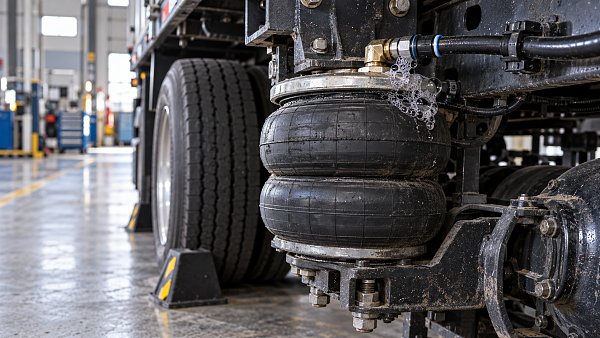
Pay particular attention to the spring’s rolling fold, the area near the piston, and locations exposed to rubbing or road debris. A crack can open only at a certain suspension position. If the leak disappears after lifting the chassis, return the suspension to a safely controlled test position using the manufacturer’s procedure. Do not exceed its travel limits or inflate an unsupported spring.
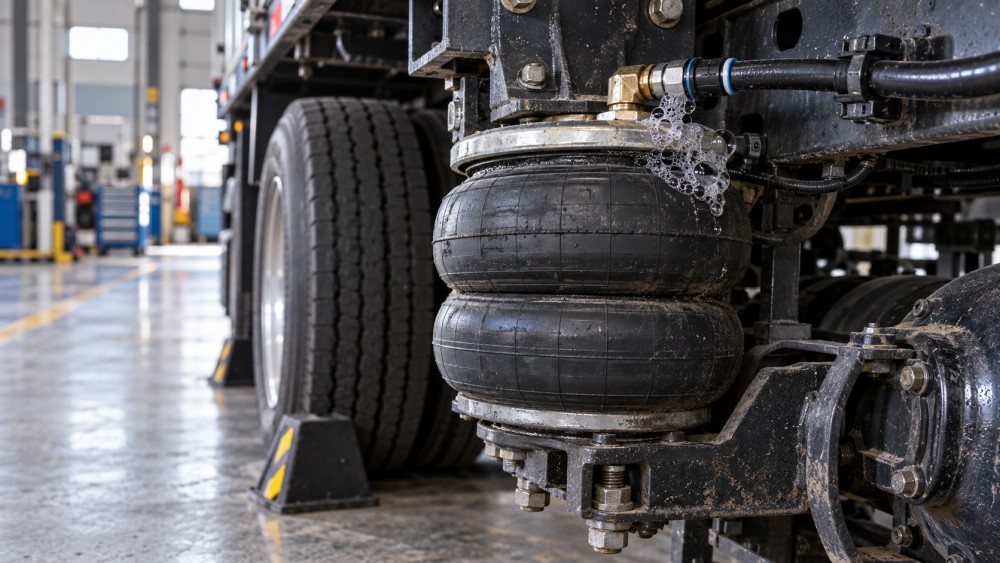
Trace tubing through clips, frame crossings, and moving connections. Abrasion hidden behind a retaining clip can be more significant than an exposed section that looks weathered. At push-to-connect fittings, inspect tube seating and alignment. Side loading, a scratched tube surface, an angled cut, or the wrong tubing specification can prevent the seal from holding.
An audible hiss identifies a larger leak, but silence does not clear a component. Slow leaks require observation time. Ultrasonic equipment can help locate escaping air in a noisy workshop; confirm the suspected location with a suitable leak test before replacing parts.
Separate spring leakage from valve and supply faults
If external inspection does not explain the loss, use the pneumatic diagram to divide the circuit into testable sections. Identify the suspension supply, height-control valve delivery, spring branches, dump arrangement, and any electronic valve block. Their connections vary, so isolation points must come from the actual configuration.
- Record a baseline. Measure ride height and pressure at approved test points after the suspension has settled. Keep the leveling and parking states consistent, and record readings over an interval suitable for the reported fault.
- With the circuit depressurized and the chassis supported, install approved isolation equipment at the specified test location. Use pressure-rated, correctly sized components. Pinching plastic air tubing can damage it and does not provide a reliable diagnostic seal.
- Observe the separated sections. Pressure loss on an isolated spring side directs attention to the springs, branch lines, fittings, or test connections. If that section holds while the complete circuit loses height, investigate the control valve, dump path, and supply arrangement.
- Restore the original plumbing after testing, then verify every disturbed connection. A temporary fitting that leaks can invalidate the isolation result.
Interpret pressure changes only after accounting for temperature and suspension movement. A supported chassis changes how spring volume responds to pressure loss. Compare tests under consistent conditions and use the manufacturer’s method instead of treating every gauge change as a measured leak rate.
Interpreting air at the height-control valve exhaust
A height-control valve exhausts when its linkage indicates that the chassis is above the selected height. Brief exhaust after unloading or settling is therefore expected. Persistent exhaust at a stable, correctly measured ride height calls for further investigation.
Inspect the linkage for looseness, bending, binding, incorrect installation, and damaged mounting points. Verify the specified neutral position and any designed response delay. A valve commanded toward exhaust by faulty linkage can imitate internal leakage. Where a dump function shares the valve assembly, trace its pneumatic pilot or electrical command as well.
If the valve continues passing air after its correct neutral and control state have been established, follow the specified internal-leakage test. Do not block its exhaust as a repair; that interferes with height control and can conceal the original fault.
When reservoir pressure also falls
Loss of reservoir pressure expands the investigation, but does not establish that the suspension caused it. Other pneumatic consumers, supply connections, or air-system components can leak independently. A large suspension leak can also draw down its supplying reservoir until a protection device closes, depending on the circuit design.
Compare pressures on the relevant sides of protection and check valves using approved test points. A leaking check valve can permit reverse flow where the design requires isolation. Verify its specified behavior rather than assuming that every valve prevents backflow in every operating state. Frequent compressor cycling during operation supports a wider air-leak investigation; it does not identify the leaking component.
Repair the confirmed fault and its cause
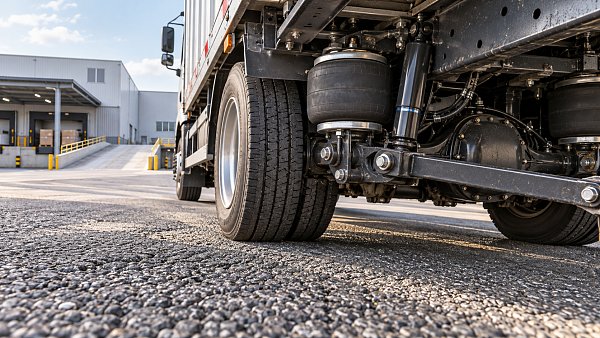
Replace a leaking air spring with the correct part for the suspension configuration. Similar external dimensions do not establish compatibility: mounting, piston shape, travel, and operating characteristics affect its behavior. Follow the manufacturer’s requirements for replacing individual springs or matched components.
Before fitting the replacement, inspect piston condition, mounting alignment, travel stops, and the surrounding structure. A spring damaged by rubbing, overextension, contamination, or incorrect ride height will remain vulnerable unless that condition is corrected. Keep the installation free of twist and use the specified mounting sequence and torque.
For tubing repairs, remove the damaged section and use approved air-system tubing and fittings. A square, clean cut and an undamaged sealing surface matter more than forcing the tube farther into a worn connector. Restore routing and support so the repaired line has adequate movement clearance without rubbing or pulling against the fitting.
Replace a confirmed faulty height-control or dump valve according to its service instructions, then set the linkage at the specified ride height. Raising the setting to hide overnight sag changes suspension geometry and can affect driveline angles, travel, and load distribution. It leaves the leak unresolved.
Verify the repair through a complete parking cycle
Recharge the system, remove diagnostic isolation equipment, and leak-test repaired and disturbed joints. Operate the suspension through its permitted leveling and dump functions, then confirm that it returns to the specified height without binding, continuous exhaust, or unexpected pressure loss. Electronic systems may require calibration or a prescribed learning procedure after component replacement.
Repeat the parking conditions that produced the complaint, including the relevant ignition and parking-brake sequence. Record initial and final ride heights, suspension pressure where available, temperature, elapsed time, and load condition. A short workshop hold test does not resolve an intermittent fault that appears only after an electronic shutdown sequence or at a particular spring position.
If work affected a shared air supply or brake-related connections, complete the required brake-system leakage and functional tests before release. Record the confirmed leak location, the repair, and the parked-height result so that any future recurrence can be compared with a documented baseline.
Send us a message
Related News
 Maintenance & TCORepair or Replace Commercial Trucks? Using Downtime and Cost per MileCommercial Trucks: repair or replace? Compare downtime, cost per mile, and future ownership costs to make smarter fleet decisions. Discover when repair pays and replacement wins.MORE+
 Medium-Duty Delivery TrucksSizing Commercial Trucks for Urban Delivery: Payload vs. Cargo VolumeSize Commercial Trucks for urban delivery with confidence. Compare payload, usable cargo volume, axle limits, and route access to choose the right fit and avoid costly extra trips.MORE+
 Highway Truck TractorsUsed Tractor Truck Inspection: Engine Hours, Fifth Wheel, and FrameBuying used Tractor Trucks? Learn how to verify engine hours, inspect fifth-wheel wear, and spot frame damage to avoid costly surprises and buy with confidence.MORE+
 Highway Truck TractorsTractor Truck Axle Ratios: Balancing Highway Fuel Use and Hill StartsTractor Trucks axle ratios affect fuel use and loaded hill starts. Learn how to compare gearing, verify launch capability, and choose a powertrain that fits your routes.MORE+
 Technology & Performance BenchmarkHow Semi-Trailer Axle Position Changes Kingpin Load and Axle WeightSemi-Trailers: Learn how axle position changes kingpin load and axle weight. Explore practical calculations to balance loads, avoid overloads, and choose the right setup.MORE+
 Box SemitrailersDry Van or Curtainsider? Choosing Semi-Trailers for Pallet FreightCompare Semi-Trailers for pallet freight: dry vans vs. curtainsiders. Discover which loading options, cargo protection, and operating costs best fit your routes before you buy.MORE+
 Full TrailersFull Trailer Coupling Checks: Drawbar Wear, Locking, and Safety ChainsFull Trailers need secure couplings for safer dispatch. Learn how to check drawbar wear, verify locking, and inspect safety chains to spot defects before they put your fleet at risk.MORE+
 Full TrailersWhat Is a Full Trailer? Axle Support, Drawbars, and Common UsesExplore how Full Trailers support loads, use drawbars, and compare with semitrailers. Discover common uses and key operating factors to choose the right setup for your freight needs.MORE+
 Refrigerated SemitrailersBuying Refrigerated Trailers for Multi-Temperature Food DeliveryBuying Refrigerated Trailers for multi-temperature food delivery? Compare layouts, cooling capacity, payload and lifetime costs to protect food quality and choose the right fit for your routes.MORE+
 Refrigerated SemitrailersRefrigerated Trailer Temperature Swings: Airflow or Unit Failure?Refrigerated Trailers showing temperature swings? Learn how to distinguish airflow issues from unit faults, protect cargo, and avoid costly repairs with practical diagnostic checks.MORE+
 Driver Assistance & SafetyFlatbed Trailer Load Securement: Preventing Steel Coil MovementFlatbed Trailers: Learn how to prevent steel coil movement with proper cradles, rated tiedowns, and load checks. Explore practical steps for safer, more confident dispatch.MORE+
 Flatbed & Lowbed SemitrailersSteel vs. Aluminum Flatbed Trailers: Payload Gains and Repair CostsCompare steel vs. aluminum Flatbed Trailers for usable payload gains, repair costs, and downtime. Discover which option delivers better value for your fleet.MORE+
 Routing & Capacity PlanningPlanning Lowboy Trailer Moves: Ground Clearance, Grades, and Site AccessPlanning moves with Lowboy Trailers? Learn how to assess ground clearance, grades, traction, and site access to avoid costly delays and keep equipment deliveries on track.MORE+
 Flatbed & Lowbed SemitrailersChoosing a Lowboy Trailer for Excavators: Deck Height and Load CapacityCompare Lowboy Trailers for excavators with expert guidance on deck height, load capacity, and axle limits. Find the right fit to avoid costly mismatches and plan your next move.MORE+
 Maintenance & TCOWhen Do Electric Trucks Pay Off? A Depot-Based Fleet TCO AnalysisWhen do Electric Trucks pay off? Explore depot-based fleet TCO, charging costs, and break-even factors to identify profitable routes and invest with confidence.MORE+
 Electric Heavy TrucksCan Electric Trucks Complete Your Routes? Payload, Range, and ChargingCan Electric Trucks handle your routes? Learn how payload, real-world range, and charging windows affect fleet performance—and discover what to check before you invest.MORE+
 Policy, Standards & ComplianceFMVSS 121 for Truck Air Brakes: Stopping Distance and Test RequirementsCommercial Vehicle Braking Systems: Understand FMVSS 121 stopping distances, test conditions, and compliance evidence to compare truck air brakes and make smarter fleet decisions.MORE+
 Braking & Electronic ControlsTruck Air Brake Fade on Long Descents: Causes and PreventionCommercial Vehicle Braking Systems can lose stopping power on long descents. Learn brake fade causes, warning signs, and prevention strategies to keep your truck under control.MORE+
 Axles & SuspensionWhy Truck Air Suspension Sags Overnight: Leak Diagnosis and RepairCommercial Vehicle Suspension Systems sagging overnight? Learn to pinpoint air leaks, identify valve faults, and verify repairs before replacing costly parts. Get the diagnostic guide.MORE+
 Axles & SuspensionAir vs. Leaf Spring Suspension for Trucks on Rough Delivery RoutesCommercial Vehicle Suspension Systems: compare air and leaf springs for rough delivery routes. Discover how payload, ride control, and maintenance shape the right truck suspension choice.MORE+