Planning Lowboy Trailer Moves: Ground Clearance, Grades, and Site Access
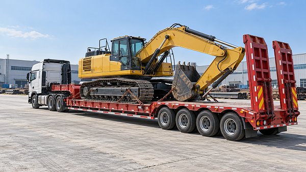
A lowboy move can satisfy payload and axle-load limits yet stop at the site entrance because the trailer grounds on a crest, the tractor loses traction, or the loaded combination cannot turn through the gate. For project managers, the useful starting point is whether the complete vehicle can travel from the public road to a stable unloading position in its planned loaded configuration.
That decision requires three connected checks: the trailer’s clearance through changes in grade, the combination’s ability to climb and descend under control, and the space and ground support available at the site. Lowboy trailers should be selected against those conditions before transport dates and equipment delivery commitments become fixed. A low deck helps with overall transport height, but it can leave less clearance beneath the trailer.
Assess the loaded combination, not the advertised deck height
Deck height describes the load platform’s position above the ground. Ground clearance describes the space beneath components that could strike the surface. These measurements answer different questions, and neither establishes whether a trailer can cross a particular entrance.
The lowest vulnerable point may be beneath the main deck, near the gooseneck, around a transition to the rear bogie, or on an exposed fitting. Its position relative to the supporting axles matters as much as its height. A low component in the middle of a long span can contact a crest even when components closer to the wheels remain clear.
Obtain configuration-specific dimensions from the carrier or trailer supplier. The planning package should identify:
- The tractor, trailer, axle arrangement, and any additional transport modules.
- Loaded ride height and the locations of low structural members and exposed components.
- Distances between supporting axle groups, overhangs, and articulation points.
- The equipment’s transport position, including attachments, overhangs, and center-of-gravity information where relevant.
- Permitted suspension or hydraulic adjustments and the operating restrictions attached to them.
Use the expected loaded condition. Suspension deflection, tire deflection, load placement, and ground settlement can reduce clearance from an unloaded measurement. Where the trailer has adjustable ride height, establish the approved travel settings and their effects on overall height, suspension movement, and stability. Available adjustment is a configuration limit to assess, not an assumed remedy for every obstruction.
Equipment positioning also affects the result. Moving a machine along the deck changes axle and coupling loads; changing an attachment’s position can alter both transport height and overhang. The carrier should validate the proposed loading arrangement before the project team treats its dimensions as the basis for an access assessment.
Survey grade transitions where the trailer could touch
A road’s stated gradient does not describe its full clearance risk. A sustained slope may be passable while a short, abrupt transition at its entrance causes contact. The survey must capture where the grade changes, how sharply it changes, and what the wheels and trailer structure will do as they cross it.
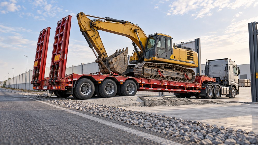
At a convex crest, supporting wheels can sit on opposite sides of the high point while the trailer’s underside passes over it. This creates a breakover risk: the ground rises into the space beneath the vehicle. Long spans and low clearance make the geometry more demanding. A raised entrance, road crown, temporary ramp, or bridge approach can create this condition without looking like a substantial hill.
A concave transition presents a different problem. As the vehicle enters or leaves a dip, a low end, overhang, or intermediate component can approach the surface. Approach and departure angles help describe some of these interactions, but a tractor-trailer has several articulated sections. A single published angle cannot establish clearance throughout the combination’s movement.
For a questionable location, record a longitudinal profile along the intended wheel paths. Include the crest or dip, the connecting slopes, and enough approach and exit distance to position the complete combination in the assessment. A level survey or suitable profile measurement provides a stronger basis than photographs alone. Images remain useful for identifying drainage channels, broken edges, and obstructions that a simple profile may omit.
Crossfall deserves a separate check. A trailer can retain clearance along its centerline while a deck edge or projecting component approaches the ground on one side. Uneven wheel paths can also introduce roll and twist. Where the vehicle turns across a sloping entrance, the relevant profile changes throughout the maneuver, so a straight-line section may be insufficient.
The carrier or a suitably qualified transport engineer should compare the measured surface with the proposed vehicle geometry through the full crossing. The assessment needs a clearance allowance for measurement uncertainty, vehicle movement, surface irregularity, and settlement. A drawing showing only nominal contact avoidance leaves little room for conditions to differ on arrival.
Do not adopt a universal “safe” grade-change angle or minimum clearance. The acceptable margin depends on the actual trailer, load, surface, and operating conditions. A location that passes one lowboy configuration may fail another with a longer effective span or a different low point.
Check traction and control separately from clearance
Passing the geometry check does not establish that the tractor can pull the load up the slope or control it on the descent. Gradient, surface condition, gross combination mass, drive-axle loading, and the tractor’s capabilities all influence the move. A short, steep entrance can be particularly difficult if the vehicle must turn, stop, or restart on it.
Ask the carrier to assess the maneuver at the intended operating speed and under credible site conditions. Wet pavement, loose aggregate, mud, or material tracked onto the entrance can change traction. A plan that depends on momentum becomes vulnerable when traffic, a gate, or another site vehicle forces an unexpected stop.
For descents, assess braking and speed control across the complete combination, including the transition at the bottom. The operator needs enough space to maintain alignment and complete the maneuver without an abrupt steering or braking input. Public-road traffic management may be necessary where the turn requires additional road space, subject to the responsible authority’s requirements.
A diagonal crossing can sometimes soften the effective transition encountered by part of the vehicle, but it also changes crossfall exposure, wheel loading, turning space, and the load’s stability conditions. It should be evaluated as a defined maneuver. Leaving the driver to improvise the crossing angle at a constrained gate transfers an unresolved design problem to the point of delivery.
Likewise, auxiliary pulling or pushing arrangements require assessment of equipment ratings, attachment points, coordination, and ground conditions. They should not be added casually after a traction problem appears. If the proposed combination cannot negotiate the entrance within its operating limits, the access arrangement or transport configuration needs to change.
Follow the swept path all the way to the unloading position
Gate width is only one part of access. During a turn, trailer wheels track inside the tractor’s path, while overhangs can swing outward. Long equipment may project beyond the deck or create a different clearance envelope from the trailer itself. Assess the loaded combination against gateposts, fencing, parked vehicles, barriers, trees, and overhead services throughout the maneuver.
The swept-path assessment should use the proposed vehicle dimensions and realistic steering and articulation limits. It should also show how the tractor lines up before entering the gate. A wide opening may still be unusable if the public road is narrow, an opposite verge cannot support wheel loads, or a wall prevents the tractor from taking the required approach.
Check these spatial constraints together with the ground profile. The route that gives the best turning clearance may place one wheel path in a drainage depression or send the low deck across a sharper crest. A turning drawing and a grade survey reviewed independently can each appear acceptable while the combined maneuver remains unworkable.
Within the site, establish which surfaces can carry the actual wheel loads. Recently backfilled trenches, buried services, culverts, slabs, and unsupported pavement edges need particular attention. A surface may look firm while lacking adequate support beneath it. Site engineering staff should assess the relevant structures and ground conditions using the carrier’s load information.
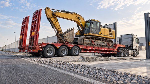
The unloading position must also suit the trailer’s operating method. A detachable-gooseneck trailer needs space and suitable support for the disconnection and loading sequence. A ramp-loaded arrangement needs room for the machine to align, cross the ramps, and reach stable ground. Ground-bearing demands can change during these operations, so the transport wheel-load assessment alone may not cover unloading.
Allow room for the equipment after it leaves the trailer and for the transport combination to depart. A delivery bay that accepts the loaded vehicle can still create a dead end if the machine blocks the exit or the tractor cannot reconnect and turn. Define reversing movements, pedestrian exclusion areas, and spotter positions before arrival.
Resolve the constraint before releasing the move
When access fails a check, identify the specific constraint before choosing a remedy. Insufficient clearance at one crest, inadequate traction on a slope, and an unsupported turning area require different interventions. Changing the trailer without identifying the cause can introduce another problem, such as greater overall height or a less favorable turning path.
Depending on the assessment, workable changes may include:
- Selecting a trailer with more suitable clearance, span lengths, steering capability, or an approved adjustable travel configuration.
- Regrading a transition or installing an engineered temporary access arrangement with verified load capacity.
- Moving the entrance or unloading area to a location with a better profile and more maneuvering space.
- Removing an attachment or changing the equipment’s approved transport position to address height, overhang, or weight distribution.
- Unloading at a suitable staging area and moving the equipment onward under a separately assessed plan.
Each change needs a review of its wider effects. Raising the trailer can reduce overhead clearance. A shorter configuration may affect load support or axle distribution. Temporary fill can interfere with drainage or fail under concentrated loading. Loose packing or an improvised ramp should not substitute for a designed crossing arrangement.
Before dispatch, issue a concise access plan tied to the actual vehicle and load. It should identify the approved route, critical profiles, turning path, unloading position, required site preparations, and responsibility for checking that those preparations are complete. Include the operating conditions that would trigger a stop and reassessment, such as damaged surfacing, standing water obscuring the route, unexpected obstructions, or a substituted trailer.
The final site check should establish that the assessed path is available: gates open fully, temporary works match the plan, the unloading area is clear, and recent excavation or weather has not changed ground support. Give the carrier and site supervisor a common contact and a clear hold point before the vehicle enters the constrained section.
Release the move when the named combination has a verified path to the unloading position and the site can support the planned operation. If a critical transition remains dependent on an unmeasured clearance or an improvised maneuver, resolve that location while the trailer is still at the planning stage.
Send us a message
Related News
 Maintenance & TCORepair or Replace Commercial Trucks? Using Downtime and Cost per MileCommercial Trucks: repair or replace? Compare downtime, cost per mile, and future ownership costs to make smarter fleet decisions. Discover when repair pays and replacement wins.MORE+
 Medium-Duty Delivery TrucksSizing Commercial Trucks for Urban Delivery: Payload vs. Cargo VolumeSize Commercial Trucks for urban delivery with confidence. Compare payload, usable cargo volume, axle limits, and route access to choose the right fit and avoid costly extra trips.MORE+
 Highway Truck TractorsUsed Tractor Truck Inspection: Engine Hours, Fifth Wheel, and FrameBuying used Tractor Trucks? Learn how to verify engine hours, inspect fifth-wheel wear, and spot frame damage to avoid costly surprises and buy with confidence.MORE+
 Highway Truck TractorsTractor Truck Axle Ratios: Balancing Highway Fuel Use and Hill StartsTractor Trucks axle ratios affect fuel use and loaded hill starts. Learn how to compare gearing, verify launch capability, and choose a powertrain that fits your routes.MORE+
 Technology & Performance BenchmarkHow Semi-Trailer Axle Position Changes Kingpin Load and Axle WeightSemi-Trailers: Learn how axle position changes kingpin load and axle weight. Explore practical calculations to balance loads, avoid overloads, and choose the right setup.MORE+
 Box SemitrailersDry Van or Curtainsider? Choosing Semi-Trailers for Pallet FreightCompare Semi-Trailers for pallet freight: dry vans vs. curtainsiders. Discover which loading options, cargo protection, and operating costs best fit your routes before you buy.MORE+
 Full TrailersFull Trailer Coupling Checks: Drawbar Wear, Locking, and Safety ChainsFull Trailers need secure couplings for safer dispatch. Learn how to check drawbar wear, verify locking, and inspect safety chains to spot defects before they put your fleet at risk.MORE+
 Full TrailersWhat Is a Full Trailer? Axle Support, Drawbars, and Common UsesExplore how Full Trailers support loads, use drawbars, and compare with semitrailers. Discover common uses and key operating factors to choose the right setup for your freight needs.MORE+
 Refrigerated SemitrailersBuying Refrigerated Trailers for Multi-Temperature Food DeliveryBuying Refrigerated Trailers for multi-temperature food delivery? Compare layouts, cooling capacity, payload and lifetime costs to protect food quality and choose the right fit for your routes.MORE+
 Refrigerated SemitrailersRefrigerated Trailer Temperature Swings: Airflow or Unit Failure?Refrigerated Trailers showing temperature swings? Learn how to distinguish airflow issues from unit faults, protect cargo, and avoid costly repairs with practical diagnostic checks.MORE+
 Driver Assistance & SafetyFlatbed Trailer Load Securement: Preventing Steel Coil MovementFlatbed Trailers: Learn how to prevent steel coil movement with proper cradles, rated tiedowns, and load checks. Explore practical steps for safer, more confident dispatch.MORE+
 Flatbed & Lowbed SemitrailersSteel vs. Aluminum Flatbed Trailers: Payload Gains and Repair CostsCompare steel vs. aluminum Flatbed Trailers for usable payload gains, repair costs, and downtime. Discover which option delivers better value for your fleet.MORE+
 Routing & Capacity PlanningPlanning Lowboy Trailer Moves: Ground Clearance, Grades, and Site AccessPlanning moves with Lowboy Trailers? Learn how to assess ground clearance, grades, traction, and site access to avoid costly delays and keep equipment deliveries on track.MORE+
 Flatbed & Lowbed SemitrailersChoosing a Lowboy Trailer for Excavators: Deck Height and Load CapacityCompare Lowboy Trailers for excavators with expert guidance on deck height, load capacity, and axle limits. Find the right fit to avoid costly mismatches and plan your next move.MORE+
 Maintenance & TCOWhen Do Electric Trucks Pay Off? A Depot-Based Fleet TCO AnalysisWhen do Electric Trucks pay off? Explore depot-based fleet TCO, charging costs, and break-even factors to identify profitable routes and invest with confidence.MORE+
 Electric Heavy TrucksCan Electric Trucks Complete Your Routes? Payload, Range, and ChargingCan Electric Trucks handle your routes? Learn how payload, real-world range, and charging windows affect fleet performance—and discover what to check before you invest.MORE+
 Policy, Standards & ComplianceFMVSS 121 for Truck Air Brakes: Stopping Distance and Test RequirementsCommercial Vehicle Braking Systems: Understand FMVSS 121 stopping distances, test conditions, and compliance evidence to compare truck air brakes and make smarter fleet decisions.MORE+
 Braking & Electronic ControlsTruck Air Brake Fade on Long Descents: Causes and PreventionCommercial Vehicle Braking Systems can lose stopping power on long descents. Learn brake fade causes, warning signs, and prevention strategies to keep your truck under control.MORE+
 Axles & SuspensionWhy Truck Air Suspension Sags Overnight: Leak Diagnosis and RepairCommercial Vehicle Suspension Systems sagging overnight? Learn to pinpoint air leaks, identify valve faults, and verify repairs before replacing costly parts. Get the diagnostic guide.MORE+
 Axles & SuspensionAir vs. Leaf Spring Suspension for Trucks on Rough Delivery RoutesCommercial Vehicle Suspension Systems: compare air and leaf springs for rough delivery routes. Discover how payload, ride control, and maintenance shape the right truck suspension choice.MORE+