Flatbed Trailer Load Securement: Preventing Steel Coil Movement
Flatbed Trailer Load Securement: Preventing Steel Coil Movement
A steel coil that shifts on a flatbed can alter axle loading, damage equipment, and create a serious crash risk. For teams managing flatbed trailers, preventing movement starts with verifying coil orientation, suitable cradles and blocking, trailer load capacity, and correctly rated tiedowns—not simply adding more chains.
The difficult loads are not always the heaviest. A smaller coil on unsuitable supports, or a correctly positioned coil restrained through weak attachment points, can still be unsafe. A reliable loading check follows the entire load path: from coil to cradle, through blocking and tiedowns, into the trailer structure.
Start with the coil orientation, not the chain count
“Eye forward” and “eye sideways” can mean different things between loading crews. Record the eye axis relative to the trailer: vertical, horizontal and parallel to travel, or horizontal and transverse to travel. A simple loading sketch removes ambiguity before the crane operator places the coil.
With the eye horizontal and transverse to travel, the coil can roll longitudinally under braking or acceleration unless its support arrangement prevents that movement. With the eye horizontal and parallel to travel, sideways rolling becomes a central concern. Neither arrangement eliminates sliding, tipping, or movement of the supports themselves.
An eye-vertical coil rests on an end face, but that does not make it inherently secure. Sliding and tipping still require assessment, particularly with a narrow footprint or a high center of gravity. Packaging, protective material, and the actual bearing surface also affect how the load behaves.
Use an orientation-specific loading plan that addresses movement forward, rearward, and sideways. A familiar chain pattern from another coil orientation is not an acceptable substitute.
Check concentrated loading before the coil reaches the deck
A trailer’s overall payload rating does not prove that it can carry a particular coil in a particular position. Coil weight may enter the structure through a short cradle or a small number of support points. Local deck capacity, crossmember loading, main-beam capacity, and the manufacturer’s concentrated-load limits all matter.
Obtain the trailer’s loading information for its actual model and configuration. A distributed-load rating cannot automatically be treated as a concentrated-load rating. Where capacity depends on a specified support length or position, confirm that the proposed arrangement meets those conditions.
Position also determines kingpin and axle-group loading. Moving a coil to satisfy trailer-axle limits may increase loading elsewhere or place the supports outside an approved structural zone. Check the complete tractor-trailer combination rather than approving the trailer in isolation.
Before loading, inspect the intended support area for damaged decking, cracked welds, distorted crossmembers, and previous repairs requiring assessment. Stop if the coil weight, support footprint, or structural capacity cannot be established. A sound securement arrangement cannot compensate for an overloaded trailer structure.
The cradle must stay put as well as the coil
Coil racks and chocks prevent rolling only when they are compatible with the coil and remain correctly positioned. Check the permitted coil dimensions, loading limits, contact geometry, and required installation method. A rack that looks substantial may still be unsuitable for the coil diameter or support arrangement.
For a horizontal-eye coil, supports should seat it as intended without unstable contact, unsupported overhang, or reliance on weak packing material. Timber used as structural blocking needs appropriate dimensions, condition, and placement under the applicable loading plan. Split, crushed, or oil-soaked pieces should not be accepted simply because they were used on the previous trip.
A common weak point is blocking that can slide together with the cargo. Verify how the racks, timbers, or chocks are restrained against the deck. Do not assume that a headboard, rub rail, or loose piece of dunnage provides rated restraint.
Friction material can help where its performance and use are established, but deck contamination changes the picture. Oil, water, ice, mill scale, and loose debris can undermine assumptions made during planning. Anti-slip material is not a replacement for required blocking or tiedowns.
Follow the restraint force through every component
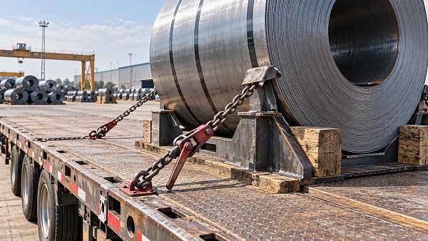
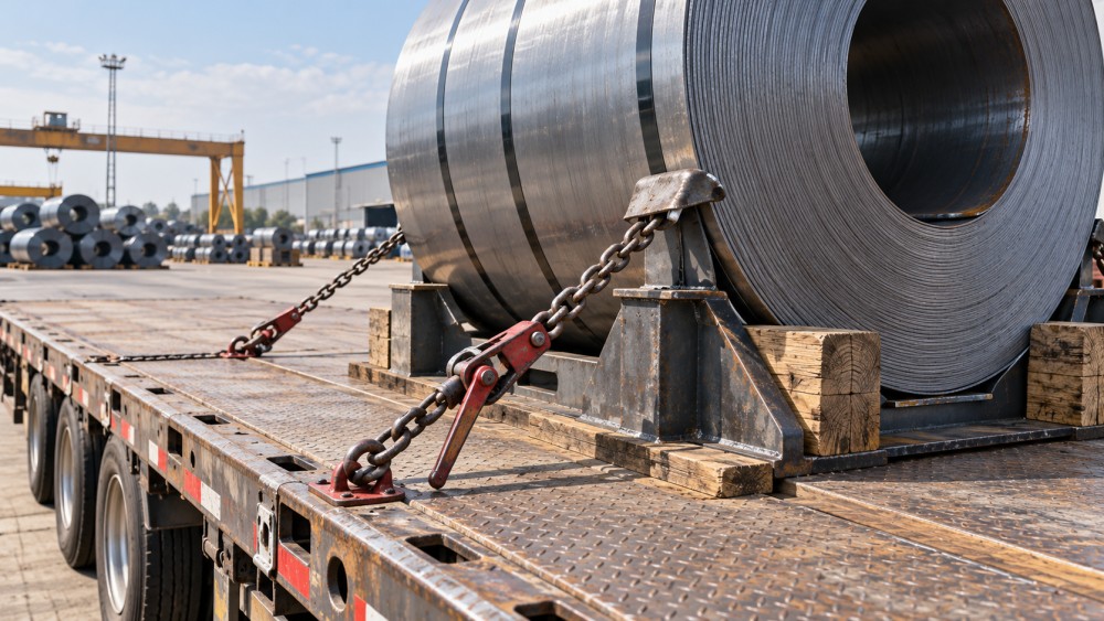
Counting chains is a poor shortcut. Effective restraint depends on tiedown direction, attachment geometry, working load limit, and the capacity of every component carrying the load. A strong chain attached to an unsuitable anchor point does not create a strong securement system.
Check chain identification and condition, binder compatibility, hooks, connectors, and trailer anchors. Use working load limits rather than breaking strength. The assembly is limited by its lowest-rated component, and damage or an improper connection can make an apparently adequate assembly unacceptable.
Geometry matters because a tiedown does not deliver its full rated capacity in every direction. A chain arranged mainly to pull downward may provide limited direct longitudinal restraint. Direct tiedowns and over-the-top tiedowns also behave differently; their ratings cannot simply be added without applying the relevant calculation rules.
Where tiedowns pass through the eye or contact coil edges, use suitable protection against cutting, abrasion, and cargo damage. Protection must remain in place under tension and should not introduce an unstable or crushable layer. Coils with exposed strip edges deserve particular attention.
Apply tension with approved equipment and methods. Improvised handle extensions can overload components or injure the operator. Secure binders against unintended release according to their instructions, then verify that tightening has not displaced a support or pulled a chain into an unsuitable contact position.
Use the operating jurisdiction’s rules—not a remembered minimum
Steel-coil securement requirements are not identical across markets. For U.S. interstate operations subject to the Federal Motor Carrier Safety Regulations, 49 CFR §393.120 contains commodity-specific metal-coil provisions. Read these alongside the applicable general securement requirements, including §§393.102 and 393.106.
Section 393.102 specifies performance criteria including 0.8 g forward deceleration and 0.5 g rearward and lateral acceleration, applied separately. These are system-performance criteria—not a shortcut for selecting a chain count. The applicable coil provisions, tiedown calculations, blocking requirements, and component ratings still need to be satisfied.
For other jurisdictions, verify the current national requirements and any standards incorporated or referenced by those requirements. A U.S.-compliant arrangement should not automatically be described as compliant elsewhere. A shipper’s loading procedure may impose additional conditions, but it does not replace applicable law.
Keep the source, revision or effective date, and scope with the approved loading procedure. For GRTE’s planned cross-market equipment comparisons, this distinction is essential: trailer suitability and securement compliance depend on country, configuration, and actual freight duty—not just a model name.
Make the dispatch inspection a release decision
The final inspection should establish whether the load matches an approved arrangement, not merely whether equipment is present. One person should be clearly responsible for resolving discrepancies before release. Uncertainty about coil weight or an anchor rating is a reason to stop, not a note to pass to the driver.
- Match the load: Confirm coil identification, weight, dimensions, quantity, and eye orientation against the loading record.
- Confirm the support: Check cradle seating, blocking retention, deck contact, and the absence of rocking or unsupported packing.
- Trace each tiedown: Verify its route, rating, attachment, edge protection, tension, and binder security against the plan.
- Check vehicle loading: Confirm the intended coil position and obtain axle-weight verification where required to establish compliance.
- Record exceptions: Resolve substitutions, damaged components, and deviations before signing the release.
Photographs are useful when they show support placement, tiedown routing, and attachment points before tarping hides them. A distant side view rarely captures enough detail. Photographs supplement physical inspection; they do not prove tension, structural capacity, or component condition.
If several coils share one trailer, inspect each coil’s restraint and the interaction between loads. Do not assume adjacent coils will act as effective blocking. A position change can affect axle loads, tiedown angles, and access to binders, so it should trigger a fresh check.
Plan for settling—and treat movement as a defect
Supports and protective materials can settle after departure, reducing tiedown tension. The route plan should provide safe inspection opportunities and access to the equipment. Where U.S. 49 CFR §392.9 applies, cargo and securement checks generally include inspection within the first 50 miles, followed by rechecks at specified duty-status changes or after three hours or 150 miles, whichever occurs first, subject to the rule’s exceptions.
Fresh deck marks, crushed timber, displaced racks, damaged edge protection, or repeatedly loose chains deserve investigation. Simply tightening a binder can conceal a support failure or an arrangement that is not controlling movement.
If movement is suspected, stop in a safe location and follow the fleet’s escalation procedure. Do not loosen restraints on a shifted coil or attempt an improvised roadside repositioning. Recovery may require a controlled area, suitable lifting equipment, and a revised securement plan.
Before dispatch, the decisive question is straightforward: can the team explain how this specific coil is supported and restrained on this specific trailer? If the answer depends on “we always use this many chains,” the load needs another review.
Send us a message
Related News
 Maintenance & TCORepair or Replace Commercial Trucks? Using Downtime and Cost per MileCommercial Trucks: repair or replace? Compare downtime, cost per mile, and future ownership costs to make smarter fleet decisions. Discover when repair pays and replacement wins.MORE+
 Medium-Duty Delivery TrucksSizing Commercial Trucks for Urban Delivery: Payload vs. Cargo VolumeSize Commercial Trucks for urban delivery with confidence. Compare payload, usable cargo volume, axle limits, and route access to choose the right fit and avoid costly extra trips.MORE+
 Highway Truck TractorsUsed Tractor Truck Inspection: Engine Hours, Fifth Wheel, and FrameBuying used Tractor Trucks? Learn how to verify engine hours, inspect fifth-wheel wear, and spot frame damage to avoid costly surprises and buy with confidence.MORE+
 Highway Truck TractorsTractor Truck Axle Ratios: Balancing Highway Fuel Use and Hill StartsTractor Trucks axle ratios affect fuel use and loaded hill starts. Learn how to compare gearing, verify launch capability, and choose a powertrain that fits your routes.MORE+
 Technology & Performance BenchmarkHow Semi-Trailer Axle Position Changes Kingpin Load and Axle WeightSemi-Trailers: Learn how axle position changes kingpin load and axle weight. Explore practical calculations to balance loads, avoid overloads, and choose the right setup.MORE+
 Box SemitrailersDry Van or Curtainsider? Choosing Semi-Trailers for Pallet FreightCompare Semi-Trailers for pallet freight: dry vans vs. curtainsiders. Discover which loading options, cargo protection, and operating costs best fit your routes before you buy.MORE+
 Full TrailersFull Trailer Coupling Checks: Drawbar Wear, Locking, and Safety ChainsFull Trailers need secure couplings for safer dispatch. Learn how to check drawbar wear, verify locking, and inspect safety chains to spot defects before they put your fleet at risk.MORE+
 Full TrailersWhat Is a Full Trailer? Axle Support, Drawbars, and Common UsesExplore how Full Trailers support loads, use drawbars, and compare with semitrailers. Discover common uses and key operating factors to choose the right setup for your freight needs.MORE+
 Refrigerated SemitrailersBuying Refrigerated Trailers for Multi-Temperature Food DeliveryBuying Refrigerated Trailers for multi-temperature food delivery? Compare layouts, cooling capacity, payload and lifetime costs to protect food quality and choose the right fit for your routes.MORE+
 Refrigerated SemitrailersRefrigerated Trailer Temperature Swings: Airflow or Unit Failure?Refrigerated Trailers showing temperature swings? Learn how to distinguish airflow issues from unit faults, protect cargo, and avoid costly repairs with practical diagnostic checks.MORE+
 Driver Assistance & SafetyFlatbed Trailer Load Securement: Preventing Steel Coil MovementFlatbed Trailers: Learn how to prevent steel coil movement with proper cradles, rated tiedowns, and load checks. Explore practical steps for safer, more confident dispatch.MORE+
 Flatbed & Lowbed SemitrailersSteel vs. Aluminum Flatbed Trailers: Payload Gains and Repair CostsCompare steel vs. aluminum Flatbed Trailers for usable payload gains, repair costs, and downtime. Discover which option delivers better value for your fleet.MORE+
 Routing & Capacity PlanningPlanning Lowboy Trailer Moves: Ground Clearance, Grades, and Site AccessPlanning moves with Lowboy Trailers? Learn how to assess ground clearance, grades, traction, and site access to avoid costly delays and keep equipment deliveries on track.MORE+
 Flatbed & Lowbed SemitrailersChoosing a Lowboy Trailer for Excavators: Deck Height and Load CapacityCompare Lowboy Trailers for excavators with expert guidance on deck height, load capacity, and axle limits. Find the right fit to avoid costly mismatches and plan your next move.MORE+
 Maintenance & TCOWhen Do Electric Trucks Pay Off? A Depot-Based Fleet TCO AnalysisWhen do Electric Trucks pay off? Explore depot-based fleet TCO, charging costs, and break-even factors to identify profitable routes and invest with confidence.MORE+
 Electric Heavy TrucksCan Electric Trucks Complete Your Routes? Payload, Range, and ChargingCan Electric Trucks handle your routes? Learn how payload, real-world range, and charging windows affect fleet performance—and discover what to check before you invest.MORE+
 Policy, Standards & ComplianceFMVSS 121 for Truck Air Brakes: Stopping Distance and Test RequirementsCommercial Vehicle Braking Systems: Understand FMVSS 121 stopping distances, test conditions, and compliance evidence to compare truck air brakes and make smarter fleet decisions.MORE+
 Braking & Electronic ControlsTruck Air Brake Fade on Long Descents: Causes and PreventionCommercial Vehicle Braking Systems can lose stopping power on long descents. Learn brake fade causes, warning signs, and prevention strategies to keep your truck under control.MORE+
 Axles & SuspensionWhy Truck Air Suspension Sags Overnight: Leak Diagnosis and RepairCommercial Vehicle Suspension Systems sagging overnight? Learn to pinpoint air leaks, identify valve faults, and verify repairs before replacing costly parts. Get the diagnostic guide.MORE+
 Axles & SuspensionAir vs. Leaf Spring Suspension for Trucks on Rough Delivery RoutesCommercial Vehicle Suspension Systems: compare air and leaf springs for rough delivery routes. Discover how payload, ride control, and maintenance shape the right truck suspension choice.MORE+